24 Cavities on a 200-Ton Press: A POM Clip Tool Built Around an Inverted Slider Core
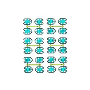
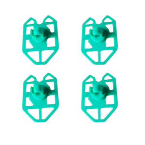
The part is an automotive clip in POM, 1 mm wall, with complex undercuts. Volumes are high enough that a single-cavity tool makes no sense. The customer asked for 24 cavities — and our job was to deliver 24 cavities their 200-ton machine could actually run.
Part
Automotive clip, complex undercuts
Material
POM
Wall thickness
1.0 mm
Layout
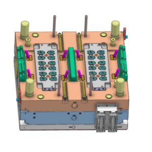
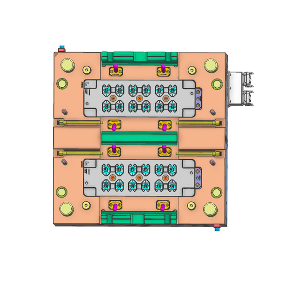
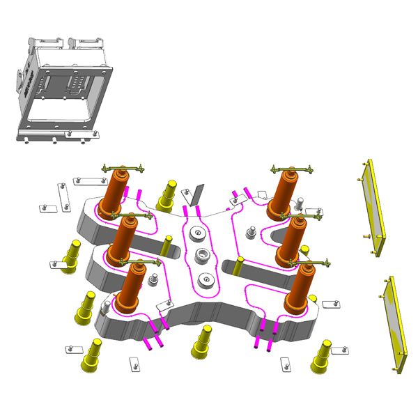
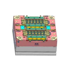
1×24 cavities, inverted tool construction with slider and lifter core
Feed system
Hybrid hot / cold runner — six hot nozzles, one per four cavities, sub-gate
Cooling
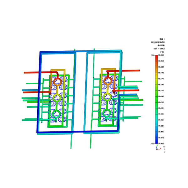
Dedicated water circuits, grouped per cavity block
Press
200 t standard injection molding machine
Surface
SPI-B1 texture
First trial
T1, signed off, moved straight to serial production
Why this tool was hard
Two requirements pulled in opposite directions.
Cavity count drives block size and shot weight, and tonnage follows. A conventional 24-cavity layout puts the projected area beyond what a 200-ton press can clamp. The usual answer is a bigger machine — capital the customer did not want to spend, and running cost they would carry for the life of the program.
At the same time, POM at 1 mm is not forgiving. Fill the cavities unevenly and you get short shots, flow hesitation where the melt stalls against a cold wall, or shrinkage that differs from cavity to cavity. On a clip, none of that stays invisible: snap-fit force varies part to part, and dimensions drift out of tolerance before the run is over.
What we changed in the construction
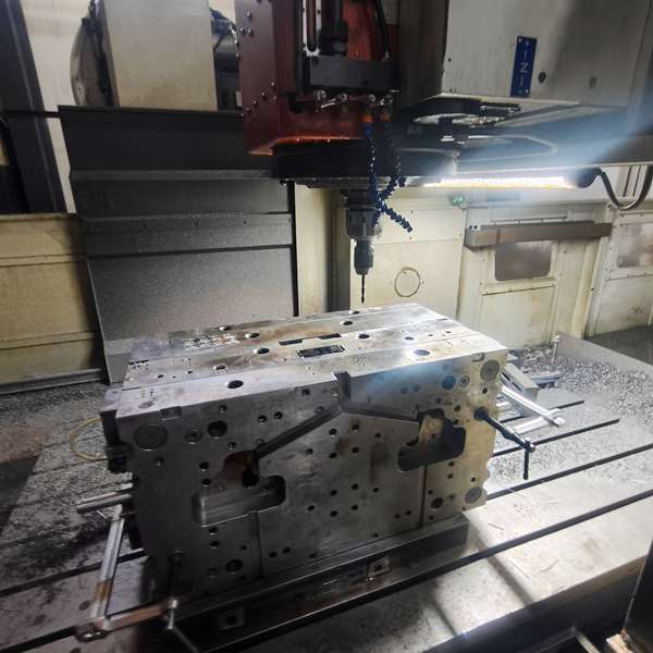
Layout. We built the tool inverted, with the slider and lifter work arranged inside the cavity block instead of hung around the outside of it. That buys pitch. Cavities sit closer together, the 24-cavity block stays inside the platen area and the clamp force of a 200-ton machine, and the customer runs the mold on the press class they already have rather than buying up.
Feeding. Six hot nozzles, each feeding four cavities through sub-gates; the rest of the runner is cold. A full 24-drop hot runner would have cost more and made the manifold harder to keep balanced. A full cold runner would have thrown away more POM and pushed injection pressure higher than the thin walls liked. Six drops at four cavities each was the point where material loss and pressure demand both stayed acceptable.
Cooling. Water circuits are grouped by cavity block, not run as a single loop through the whole tool. Every group holds the same mold temperature, so all 24 parts see the same cooling curve. This is the part of the design that keeps shrinkage consistent across the layout — and it is usually where thin-wall POM tools lose their dimensional repeatability.
Simulation before steel
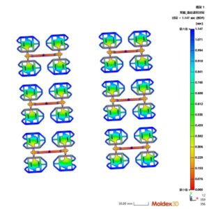
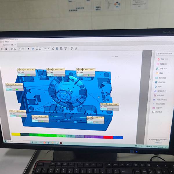
Before the block was cut, we ran moldflow on the layout: melt front position over time, fill pressure at each cavity, and the pressure difference between the first-filled and last-filled cavities. Those numbers decided gate sizing and where the cooling groups needed to be split. Balance is cheap to fix in software and expensive to fix in hardened steel.
Result
The tool passed T1 on the first trial and went into serial production without a second trial round. Parts come off with SPI-B1 texture and hold the customer’s automotive dimensional tolerances.
Working on a high-cavity tool your current press may not clamp? Send the part drawing and your machine spec. We will tell you what cavity count the tonnage supports, and where the layout has to change, before you commit to a tool.